BLDC Motor Controller: Component Selection
This article is part 1 of a series in which I will track my progress in the creation of a STM32-based ESC motor controller. The board will be designed to test various (sensorless) motor control algorithms like 6-step control and FOC (field-oriented control).
I defined the following requirements:
- 3-5S LiPo input (11.1-21V)
- 45A continuous current
- Current & voltage sensing on all phases + Back-EMF sensing
- CAN, USB, & hall sensor interfaces (+ maybe I2C/SPI/UART)
- 6-layer board, 2oz on outer layers, 0.5oz on inner layers
- Minimal form factor, majority of components on top layer
Some interesting resources I found and will consult during the design are the open source VESC project and the STMicroelectronics B-G431B-ESC1 discovery kit. Both have detailed schematics and documentation available.
Microcontroller
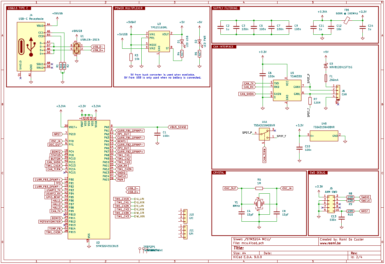
For the brains of the ESC, I chose a microcontroller from the STM32G4 series by STMicroelectronics. These MCUs are designed with motor control and digital power applications in mind, offering a solid blend of performance and analog capability.
Specifically, I went with the STM32G431CB.* It’s an entry-level chip that brings together a Cortex-M4 core with DSP and floating-point unit (FPU) support—handy for fast real-time calculations. One of the key reasons for this choice was its rich set of analog features: it includes three 12-bit ADCs and four programmable op-amps, which are perfect for precise current shunt measurements.
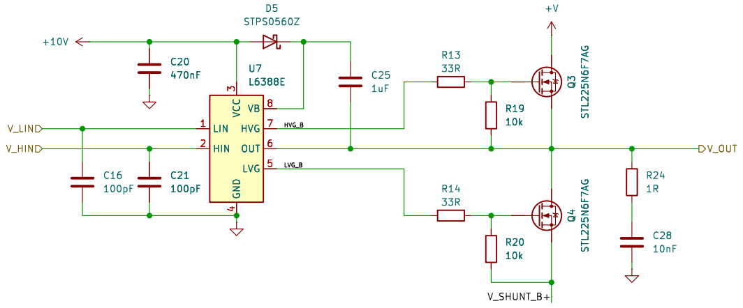
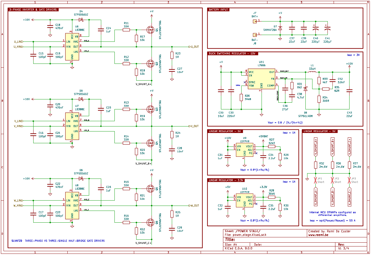
MOSFETs & Gate Drivers
When it came to selecting the power stage components, I focused on finding MOSFETs with high current handling, low on-resistance, and a comfortable voltage margin. Since the ESC is designed to operate at a maximum voltage of around 21V, I wanted components that could easily withstand voltage spikes and transients. I settled on the STL225N6F7AG, a 60V, 120A MOSFET with a very low 1.2 mΩ RDS(on). These specs provide plenty of headroom while keeping conduction losses to a minimum.
For the gate drivers, I chose to use three individual half-bridge drivers instead of a single integrated three-phase driver. This might seem unconventional, but it offers a significant layout advantage: it allows me to place each driver closer to its corresponding MOSFET pair, which gives a bit more flexibility in routing. I picked the L6388E which is rated for 600V and has 400mA source current and 650mA sink current capabality.
 |
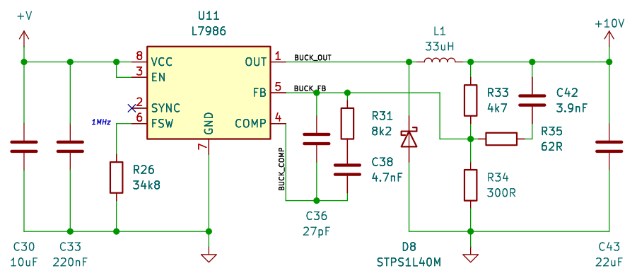
Power Control
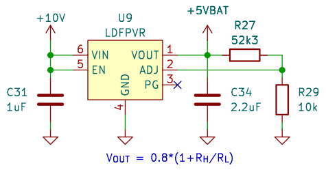
A L7986-based buck regulator will converter the input battery voltage to a stable 10V reference. The 10V is used directly by the gate drivers, and is reduced to 5V and 3.3V by LDFPVR linear regulators.
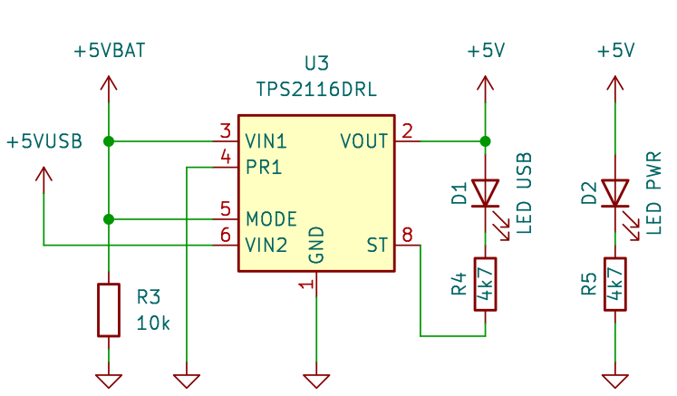
There is also a USB-C 2.0 receptacle on the board which is able to communicate with the MUC & power the peripherals (5V & 3.3V) when no battery is connected. The TPS2116, a low IQ power multiplexer is used to switch between USB power and battery power, prioritizing the battery power if available.
 |
 |
 |
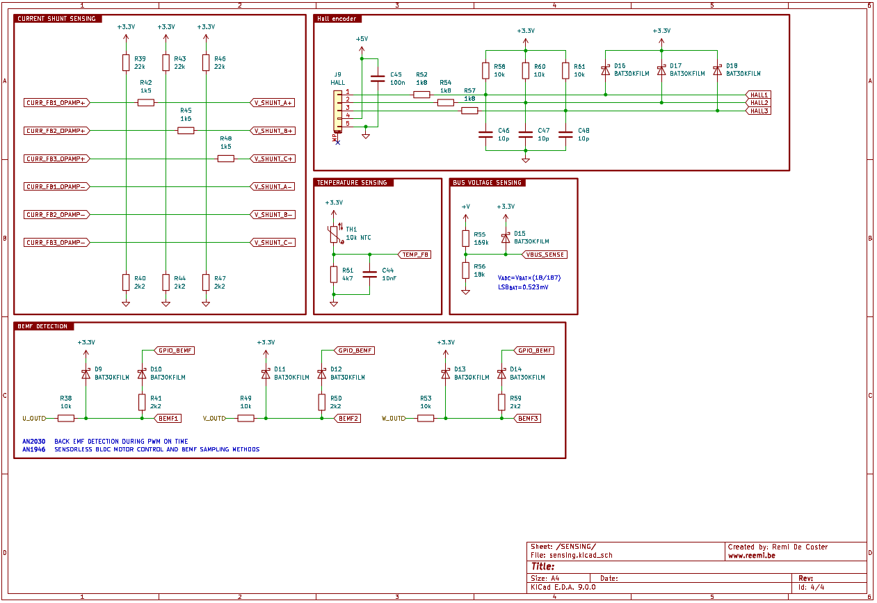
Sensing
The current is measured in each phase of the motor controller by using a low-side shunt resistor of 2mΩ in each half-bridge. Two current shunts would be sufficient (sum of phase currents equals 0), but this allows for higher accuracy. The internal op-amps of the MCU are used to amplify the measurement. The voltage of each motor phase and the battery voltage is measured using a simple resistor divider.
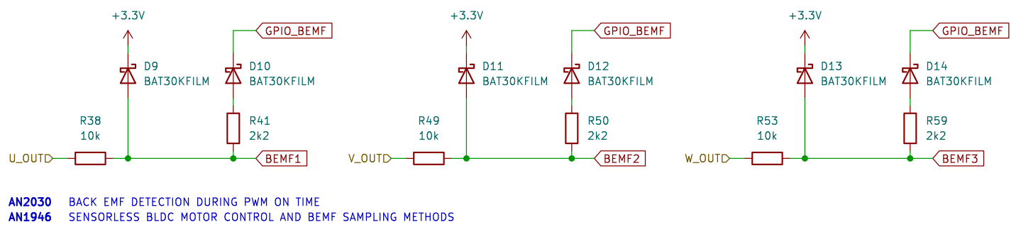
Measuring the back-EMF is interesting for sensorless control as it is directly related to the rotor’s position and speed, and can thus be used to determine the commutation sequence. In application notes, I found an interesting schematic which allows the back-EMF to be measured in two modes. Either at the end of PWM at low duty cycles (low speeds), or during the PWM at higher duty cycles (high speeds).
 |
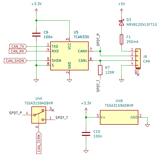
CAN Interface
A TCAN330 transceiver module is used to enable the CAN peripheral. A fuse is included to protect the connected bus if anything were to go wrong with the motor controller. The circuit accepts also the supply voltage from the external unit. A terminator reistor of 120Ω can be enabled or disabled by the MCU by integrating a digital SPDT switch.
 |
Next up
That’s it for the most important components on the board. The full schematics will be made available on GitHub soon.
 |
 |
 |
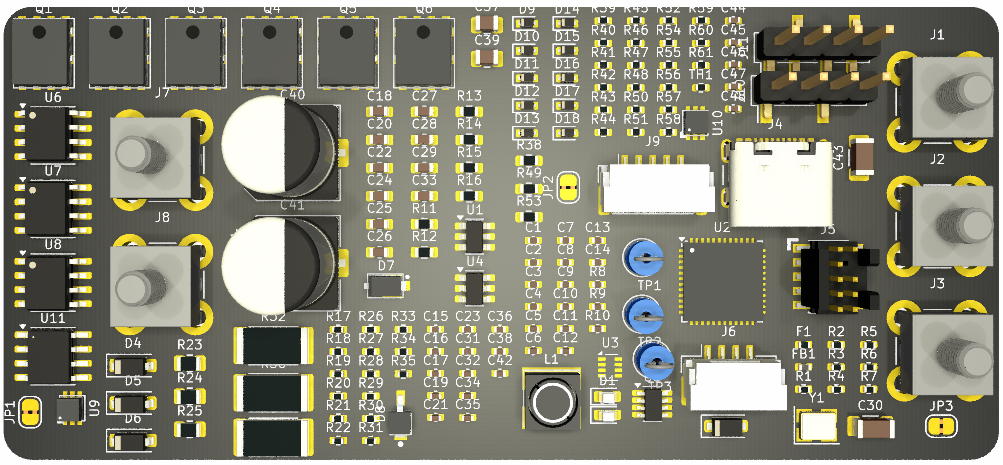
Time to start on the layout!